Cj Cp Run time Totalizator and Pulse counter [Pw C]
D Da DS Data mode & GPRS setup [Pw D]
Internet client mode & setup [Code i]
Err Contrôle du programme de fonctionnement [Pw err]
Se Sx Si Status Power Meter [Pw SE]
# Send serial port input as SMS to N1 [Pw #]
& Direct AT commando, SMS to GSM radio [Pw &]
W Direct Read Write to controller memory [Pw w X]
PWM Pulses Wide Modulator [Code PWM]
CMP Compare Function (at FW1) [Code CMP]
These software functions will not be used often but they are nevertheless accessible to the user. Do not hesitate to contact us for more details or information.
The GXL88 has many new functions that were missing in the previous GXL8x! Please make sure that you are consulting the correct manual for the old GXL8x or for the new GXL88 to match the controller used ...
Programmable Restriction and BLOKKER when switching Rn.
We only will see the command for R1. R1 and R2 having identical commands. So the three fields JRn command [Pw JR1 3 65 10] setup a "Off" restriction for R1 and a control for R1_L1 with alert to number 10.
(65) Control Rn_Ln that can have values 0, 1 or 2 to 250. Control L1 for R1 (L2 for R2).
(10) List number to be Alerted. Points to the list number where to send the Alert.
Restrictor OFF here to 3, will force check R3 before any junction action on R1 so that R1 can only go Off if R3 is Off. All relais can be used as restrictor except R1 (or it will remain to ON). Direct commands like [Pw R1 off] [Pw R1 (timing)] still work and always can switch it off.
Control R1_L1 makes send Alert (to number 10 in this example) after junction switching of R1 if after 65 secondes no power appears on L1. Another adaptor on L1 with negative on T34 and positive on Terminal T35 can be used for this test.
Timing can be 2 to 250 seconds before the test occurs on L1 after junction switching of R1.
Control Rn_Ln set to 1, prevents R1 junction switching to On if L1 already has power (T35).
The list number to Alert can point to any list number 1 to 63. As for other junctions, the number can be replaced with any valid direct command when wanted.
So [Pw N53 =R4 600 s] will write direct command "R4 600 s" into list number position 53.
This could switch R4 On for 10mn and send a status message if L1 has no power 65s after that a Junction has switched R1 On.
Actual configuration of Restriction and Control parameters are listed and visible in info message J? [Pw J?] and Jls [Pw JLS]. Alert message a) Rn ON but No Ln Power after; XX sec! will also include parametres JR1/2 R SSS N and controller time at the Alert.
C
Run time counter and Totalizator.
Info's with [Pw
C?]
A daily run time counter and totalizator,
that can be
virtually "connected" to one of the inputs i1 to i7 or An, Ln, Vn, Tn,
G or Y, is available.
Count will occur on a defined input level. For example, if L1 is
setup as
the counter input, count happens as long as L1 is powered. If no power,
it will
stop and will count again when re-powered. Count is accurate on the
minute. Status
(if CJ+) and infos SMS [Pw
C?] show the daily counts 0-24H and the totalizator.
Command [0000 Cj 11] for
example will internally connect the run time counter to input L1.
Number 11 here is simply refer
to the junction number. So choosed inputs can be; A1(1) à A7(7),
AC(10),
L1/2/3(11/12/13), V1/2(14/15),
T1/2(16/17), G(18), Y(19).
Status (if CJ+) and infos SMS [Pw C?] show the daily counts 0-24H and the totalizator.
Pw Cj 12
Actual input (L2)
for
counter Cj
Cj;
1-19 Possible Cj inputs
Cd
03:09 CJ
count for this day
CT
56:52 CJ TOTAL count
XXXXX:XX
Cjz
0 Tot=0:00
with [Pw CJz] or [Pw CJz 250]
Pw Cp 6
Actual input for counter Cp
Cp;
3,6 Possible Pulses counter inputs
Pd 0
Cp count for this day
PT -1
Cp TOTAL count
XXXXXXXXXX
Cpz Total ZERO! Total=0
with Command [Pw Cpz]
CpS
5 Input for pulses
decounting, 0 or 5
Cj- Cp- [Pw Cj+] [Pw Cp+] add to status.
When chosen for the run time counter, Cj inputs i/A2, i/A4, i/A6, L1, L2, V1, V2, T1,
T2, Gl
and Yg will count when the input shows a High or On level (when
12Vdc power is on L1 for example)
Inputs i/A1,
i/A3, i/A5, i/A7 and L3 will count for low level or OFF.
Pulse Counter and
Pulse totalizator. A
daily
pulses counter and totalizator can be
setup for input
i/A6 (pulse to GND) or L3 (voltage pulse +8 to +24V).
[Pw Cp 3] [Pw
Cp 6] Pulses are added to the daily pulses counter and added
to the totalizator at 29:59+1. [Pw Cps 5]
makes that other pulses at input i/A5 will be substracted from the
daily
pulses counter
and subsequently
from the pulses totalizator also at 29:59+1.
Data connection au réseau GSM. GPRS ou WEB [Pw da] [Pw Ds]
A partir de version V1301, les messages peuvent étre envoyés en format GPRS sur le réseau GSM. La fonction est supportée pour les contrôleur type GXL83-x que SI le module radio+SIM incorporés supporte le mode GPRS.
Commande [Code &AT+CGMR]qui donne la version du module radio indiquera si oui pour les versions B20e00gg.WISMO228 (module 4 bandes (+USA) et version L22_00gg.WISMO218 et suivant pour tous les GXL83-2 et la pluspart des GXL83 (trais bleu sur les relais).
En cas de mise à jours des GXL83 à V1301 et + il sera absolument nécessaire d'executer la commande [Pw FSRA] aprés quoi.
DaL "vodaphone" Login name
DaW "vodaphone" Password
DaS "83.163.123.80",5000 Ip et port to connect to
Dai Tombouctou-05 L'identifiant du contrôleur et/ou sa location.
<48<24<24<48<24 mémo, longueur permise de characters
DaT 0 DaO 10 Dat pour GPRS On/Off. Le temps en ligne
Tombouctou-05 Le identifiant/location du contrôleur
355915030625941 IMEI.
Pour supprimer le nom du contrôleur envoyer [Code dai ] et bien noter l'espace standard suivant le nom de la commande mais surtout le suivant qui annule le nom du contrôleur.
Pour les 4 premières lignes, les " sont indispenssable et à inclure à la commande. Donc on envera; [Pw dan "APN" das "55.163.123.80",2200]. Le nom et IMEI seront inclus à tous les messages GPRS afin d'en facilement reconnaitre l'expéditeur lors du traitement.
<<<Tombouctou-05(CR)355915030625941(CR LF)
R1 OFF(CR)R2 ON(CR)R3 555(CR)R4 ON(CR)R5 OFF(CR)V1 12.2(CR)V2 55.1(CR)V3 13.0(CR)AC 1 00T(CR)G 22.6%(CR)0-7: 11100111(CR)A OFF M0(CR)14:53>>>(CR LF)
En mode DATA (donc si DAT = 1 [Pw Dat 1]) tous les messages destinés à N1 sont redirigés au serveur (N1 est donc alors requit). Les autres de N2 à N49 sont transmis par SMS au numéro en liste correspondant. Les demandes envoyées par SMS au contrôleur sont elle répondue via SMS
Le contôleur peut être ordonné par exemple [R1 off r4 44 s] ou configuré via l'interface serveur si capable d'envoyer les commandes. La commande [Pw Dac] via SMS force le connection au serveur si déjà configuré par une autre SMS et que DAT et >0.
Le temps de connection active DaO peut être ralongé pour avoir le temps d'écrire et envoyer des commandes en retour au contrôleur manuelement. Donc la commande de demande de connection data par SMS pourrai étre [Pw DaO 60 Dac] ce qui donnerai 1 mn de temps de connection (et de nouveau après chaque data commande). Le contrôleur coupera alors la connection "data active" et retournera en mode SMS aprè 60 secondes si aucunne autre commande n'est recue.
Maintenir DaO le plus court possible (6 à 10) (10defaut) afin de ne pas perde de temps au cas ou le contrôleur devrai envoyer des SMS à d'autres numéros que N1 ou si des messages sont en attente d'être envoyées. Pour ce on pourrai terminer la commande data par [R1 off r4 44 DaO 8]
<<<Tombouctou-05(CR)355915030625941(CR LF)
>>>Waiting for COMMANDS (Check DaO tming)!>>>(CR LF)
Les commandes peuvent alors être envoyées en data mode au contrôleurs, manuellement ou bien sur encore automatiquement à partir de l'application tournant sur le serveur qui ne nécéssite alors qu'un temps DaO trés court. Ce dernier peut même couper activement la connection, action reconnue par le contrôleur qui retournera délors en mode SMS. Example de commande: [R1 55 R3 off s]. Les [] sont à inclure quand on envoie en mode data. (pas en mode SMS).
[Pw Ds] local serveur fonction. (spécific voir i? pour usage courant)
DsL "Any_name" Login name. 23 characters maxi
DsW "MOTdePASSE" Password. 23 characters maxi
<32<24<24 mémo, longueur permise de characters
DsT 0 Local GXLxx serveur fonction active
Tombouctou-05 Le non/location du contrôleur
355915030625941 IMEI.
i Configuration internet and controller in client mode.
As already seen in the GXL88 manual the controller can also advantageously be controlled via the internet. A fixed IP address is preferable and strongly advised in order to connect to the server inside the controller who will then serve the web page on request trough the web to your brouser.
Since the controller will be queried for example by http://53.123.234.50:1453/Page_Name and it will be necessary to know its IP address, 1453 being the access port and Page_Name which will be the (optional) name of the page chosen by the user (see ipn).
For the normal Internet mode, refer to paragraph i of the manual and operate this mode and be sure to make it work before reading and trying the special functionality described below.
Contrary to the normal mode above, the GXL88 controller in client mode will send the information messages to an external server via internet at some time intervals depending of the config. The GSM modem and SIM are no longer required at this point but can nevertheless be used as well together with the internet client mode.
Let's first see the list of the controller internet parameters and then the parameters of the Internet module (M53 or other) .
[Code i] liste de configuration internet du contrôleur
iCA 88.160.241.20:1425 GXL88 server address Ip:port where to connect from your browser.
iSA www.nnnn.com/name Address where GXL88 must connect in client mode (config via Ez)
iPN Page_Name The name (or number) of up to 15 characters from the GXL88 internet page.
iSL no_name The user name in client mode. *
iSW no_pass The password in client mode. *
iPR 0 Optional, self-reload of the browser page in (Mode i1) *
iPT 0 Maximum connection waiting time for mode i2. * =Optional!
2x<32 3x<16 >4s >2s String length (chrs) of ICA/ISA IPN/ISL/ISW and IPR 4, IPT 2sec minimum.
iPB 7 GXL88 <=> M53 communication, 7=57600b/s default do not change for now!
i = OFF Says if internet is activated by [code i ON], [code i2] or by [code i3].
The first 7 parameters above are not to be considered in i2 or i3 mode if the Internet module used is the M53 as all these settings are made at module level itself using EZ MANAGER. This from a PC connected on the local area network (LAN).
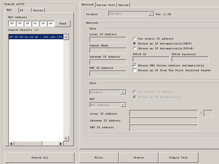
We will go to next step only after having succesfully made run the Internet mode of the controller initiated by the [code i on] command. Cobfiguration of the M53 internet module with the ez manager program was also needed to make the internet work in mode i ON or i1 as described in paragraph i from the normal manual...
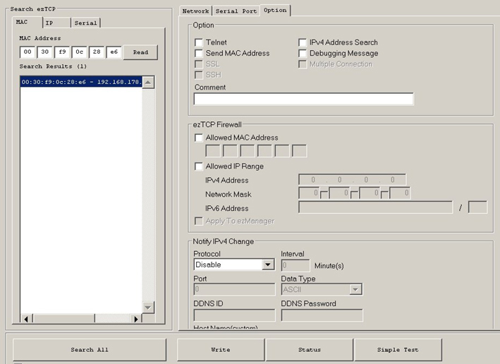
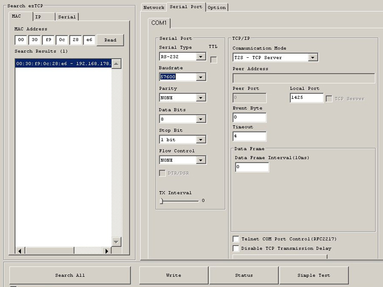
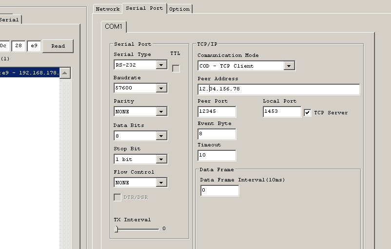
Start Ez Manager again in order to change the mode of the M53 from server to client mode. Tabs 1 et 3 will remain with same parameters but Tab 2 will have to be changed according to the parameters described below and visible on this image.
"Peer Address" will be the IP address of the server where the GXL88 will periodically send its Alarm, Alert, Warning and divers messages and Status.
"Peer Port" will be the (open) port of the server where messages will be received, processed, retained.
"Event Byte" will be set from 4 to 10 and "Timeout" from 2 to 10 (see the details on the M53 doc).
First interesting details is the validation of "TCP Server" which will give the possibility to access the controller in current mode but still working in client mode sending its messages to Peer adrs + Port! This dual mode can be used at the configuration time which will be done easily by the Internet. These modes do not work simultaneously, and at least the timeout (from the M53 TCP module) as well as timing IPT and DAO (from the controller)) must always be awaited for for correct traffic. This can be controlled on the UTP socket LEDs and the middle LED of the controller.
In order to validate this client mode also into the controller, it will be necessary to give the parameter i which was in the normal Internet mode at "i ON" the value i2 or i3.
[Code i2] forces a reset of the M53 and makes a DHCP reconnection to the router before sending a message and [Code i3] will force the re-initialization of the Internet module and the connection after sending the message. To check for your own need but mode i2 gives good result so far.
However internet module reset and initialization could also be done automatically on short time laps with a local command. So as an example, sending command [0000 hs1 11 0 0 hsm 45 n11 =i2] will force execute the command writen at position 11 in the phonebook every 45mn again and again. This methode will probably never be used because i2 and i3 take care of the reset before and after sending a message but could be used in with i1. Remember also that no activity on the LAN also force a reset and initialize. So wait for over 60mn may the controller not respond any more via internet. See also at i? in the manual for the basic i info's.
Second interesting detail is the direct command mode via internet when the M53 in server or client/server mode and the controller in i mode ON or I2 or i3.
Indeed, the Internet access to the controller normally fed by http://ip.ip.ip.ip:port/Page_Name (the page name parameter is optional (see ipn) will return a web/html page generated by the controller himself.
If the page name is replaced by a - followed by the code (same as with SMS) and the wanted command, the feedback will no longer be graphic but only textual just like a SMS but this time on the internet and on the browser screen! (Browser like FireFox, netscape, Safari, SeeMonkey are advised but not IE).
So sending http://ip.ip.ip.ip:port/-0000 r3 3600 r1 11 ss by the address bar of the browser will return a short message type SMS but then on the screen. As by SMS, PC or i ON, all commands are allowed by this mode so be careful.
Operating of the GXL88 in client mode via internet can be compared to the GPRS mode which also can regularly send its information to a server listening somewhere on the Internet.Client mode and GPRS send identical messages format is in both cases. .
- If the SIM mode is 0 and the internet mode is i2 or i3, the IMEI number of the GSM modem can not be read since the controller is running without GSM connectivity and hardware because SIM is at zero*.
The IMEI displayed in certain messages will then be replaced by IPN also able to count up to 15 characters. See i? for IPN and G? for the IMEI. (One could write the IMEI visible on the gsm modem chip itself at IPN when wanted)
- The middle LED of the controller lights up /blinks red+green alternately at the rate of 1 quarter of a second until iPT time, the message is then sent by ip and the controller returns to standby for the DAO time with only the green LED on (Dao time is as when using GPRS the time to wait for an automated or manual [code command] from the server side).
While normally 25 consecutive trys are carried out to connect to the GSM network with sim 1, 2 or 3 and i0 or 1), only 5 tests will be carried out if the parameter i is i2 or i3 however the SIM parameter value. See also in G?
- The status messages on line HH:MM M0 is modified in HH:MM i2/s0. The M becoming obsolete when sim=0, the i parameter value will be indicated followed by the sim mode value...
* Let us recall that in mode sim = 0 the GSM modem can however be started manually with the [Code fg]. Since SMS can also be received by the controller even in different internet mode this could help in various tests or configuration if a SIM is in place...
* You can manually start the GSM modem in SIM 0 mode to get the IMEI number without SIM or if necessary to read it on the GSM chip.
A8 was not accessible and so not connected to terminal (50) on versions prior to 2017 but was used internally. So please leave A8 at zero in menu A? in such controller version.
Err Monitoring and memory Error Check.
Pw!=47
Irq=379
GSM=11
Sys=48 Auto+forcé système restart compte F?
GPRSerr=0
GPRS ok=0
GPc=28
10000101
00100010
10100001
sErr=11
ErT:0 at:0
GXL88 V2-15
Found Error can be send via SMS at number present at position 34 in mumber list.
* Redirect received SMS to the serial port. [Pw *?]
Any controller incoming SMS message will be redirected to the RS232 serial output when the SMS message starts with character *.
Output will be at 9600 B/s, no parity and 1 stop bit and 5V level. The controller will do nothing else with the message but transmit it to the serial...
This function can be used when a PC is connected to the controller serial output via our optional interface cable.
So following SMS message to the controller;
[0000 *Any message until 150 characters...] 0000 is the default password, 1sp, *and the text.
will shows *Any message until 150 characters... on the PC screen.
# Send serial port input as SMS to N1. [Pw #?]
Any string sent from PC to the controller serial port will be sent as an SMS to number n1 if it starts with character #. Pw is not needed before the string of 155 characters maximal, which header's will be #.
This function only makes sense when a PC/laptop is connected to the controller serial at same baud rate, 9600b/s NP 1Sb and that (hyper)terminal or any other advanced communication program is running. Chr# is removed from the SMS message when sent, the number where to send will be at N1.
So sending from the PC string; #This is an SMS message to an other mobile...
Will make mobile pionted by N1 receive; [This is an SMS message to another mobile...]
Any string of characters can be sent as SMS from the PC, so the controlleur can be used as an PC SMS CONTROLLER as well!
So as an example, string; "#0000 R1 180" from PC* will make send SMS [0000 R1 180] to N1.
(This could Set output O1 for 3mn of an other far away controller if N1 was its SIM number!)
*Any command or SMS message can be sent that way, local or from elsewhere. #SMS from another phone to the first controller (attached or not the a PC) can receive the SMS and forward it to another number. So: [0000 #0000 R1 180 s] can do it from any place (Pw is needed for any incoming SMS, not for the serial link to the PC). Using our (free) GAR program will make all much more simple when connected to the PC.
Notice here that field N (that normally vectors to the number to be alerted) can also force a local command and therfore also make sent any short text on a Junction trigger. So if N61 is [N61 =#Send 13c maxi] Trigger on J will send it to N61.
& Direct AT commando from SMS to the GSM engine. [Pw &?]
This function must be used very carefully, because any wrong AT commando to the built-in GSM engine could make the controller stop all communication until power off and on again or for ever. It is highly advised to study the engine data sheet before using this function. However, the function is locked by default to prevent any mistake remotely via SMS, but it is free to use without restriction and at your risk with the PC program.When unlocked for SMS (ask us), power up the controller or simply wait the next hour will disable the function.
[Pw Ww 97 111 &AT+CSQ] , will return the radio signal level via SMS.
[Pw &AT+CGSN] , return the SIM IMEI number.
[Pw &AT+CREG?] , return the registration type. (x.1 local) (x.5 roaming)
[Pw &AT+VGT?] , will return MIC gain level.
The controller checks if the GSM radio is still registered to the network each hour. If not, it will try to register again. So in case of no contact to the controller wait 1H and try again. It then should be online (registered) again.
W Direct Read Write to controller memory. [Pw w?] [Pw x?]
This function will only be of interest when enabling some controller special features. So we can list any eeprom (w) locations or the static ram (x) or also (very carefully!) write some bytes in there.
Command "Pw Ww Adr Value" can be useful in order to change some controller behaviour...
- Set output(s) to ON at Init and startup.
- Changing the Mn value (default 0 or 9 at Init).
- Changing the test if registered to network time (default at HH:22).
- Changing the Output OFF indication by O (default OFF) to save space in lines and SMS.
- Setting the "No SIM" option, and more...
So, to read the eeprom from 60hex, send [0000 wr 60] you get SMS;
0060:
00000000000000000000000000000000
4F310020464748004700FFFFFFFFFFFF
4F3200FFFFFFFFFFFFFFFFFFFFFFFFFF
4F3300FFFFFFFFFFFFFFFFFFFFFFFFFF
To Rd the SMS waiting to be send in the controller TX buffer; [Pw Xr A00] you get back;
0A00:
4B0D2B435245473A20302C310D4F4B0D
2B5647543A2031300D4F4B0D416C6765
6D65656E220D2B435042523A20372C22
2B3331363534383031303331222C3134
To enable any write to the eeprom, (and the ATCommand) an unlock command needs to be sent first (just ask us for it). Most changes to the eeprom parameters require a program startup before taking effect. Use therfore; [Pw Fz].
Waiting the next whole hour HH:59+1 or [Pw Ww 40 0] disable the write-to eeprom function.
SE SX SI Power Meter
Attention! This Energy modules should only be connected by qualified
electricians! Any connection or manipulation to the 220/380/440 grid power or a high
tension generator presents real
danger and electrocution risks!
I1 10.4 Phase current, Ampères (via CT).
I2 11.0 Phase current, Ampères (via CT).
I3 9.9 Phase current, Ampères (via CT).
U1 230 Phase voltage, Volts (directly connected).
U2 233 Phase voltage, Volts (directly connected).
U3 229 Phase voltage, Volts (directly connected).
L1 382 Phase line voltage, Volts (directly connected).
L2 384 Phase line voltage, Volts (directly connected).
L3 380 Phase line voltage, Volts (directly connected).
P1 10000 Phase active power Watts (internal calculation).
P2 11000 Phase active power Watts (internal calculation).
P3 12000 Phase active power Watts (internal calculation).
PT 30000 3 Phase total active power Watts (internal calculation).
QT 440.24 3 Phase total reactive power VA (internal calculation).
ST 28000 3 Phase total apparent power VA (internal calculation).
FT 0.90 3 Phase total power factor (internal calculation).
FQ 50.01 Frequency (internal calculation).
KW 552416.6 KWH. 99999999 maxi totalisator, can be reset via SMS.
Displayed measured values, above and below, are only examples and not real values. The order and quantities can differ depending on the connected energy power meter.
L1 382 Phase line voltage.
L2 382 Phase line voltage.
L3 382 Phase line voltage.
PT 6789 Total active power.
Q1 333.30 Phase reactive power.
Q2 44.44 Phase reactive power.
Q3 25.00 Phase reactive power.
QT 500.00 Total reactive power.
F1 1.00 Phase power factor.
F2 0.90 Phase power factor.
F3 0.80 Phase power factor.
FT 1.00 Phase power factor.
S1 11000 Phase apparent power.
S2 11000 Phase apparent power.
S3 11000 Phase apparent power.
ST 33000 3 phase total apparent power.
FQ 50.01 Frequency.
KW 552416.6 KWH. Totalisator. Can be reset to 0.0 via SMS.
Read or connection error will return following SMS to N33 (if a phone number is put there at this list index) or to the server when working in the GPRS mode:
Power Meter ERROR!
Check if PM is connected, AC powered and the RS232 link PMC<>GXL8x! 19:03
GXL88-2015

The controller can be easily configured for an automatic emission of a Status Energy (Se) each hour or each day (See chapter H? and [Code Hse N HH:MM]). The direct SMS commands [Code se] and [Code sx] simply immediately replies to the number that requested the infos to the controller. The Energy Power Meter will be connected to the SMS controller with the delivered cable.